The features that we wanted the PCB to have are as follows:
- Header and bolts to enable a Raspberry Pi to be firmly attached.
- Header and bolts to enable an iC880a to be firmly attached.
- Mounting for a battery backed RTC to provide a constant time source.
- Mounting for a temperature/humidity sensor.
- Connection between the PPS pin on the iC880a and the Raspberry Pi.
- Connection from the optional ublox GPS module on the iC880a to the Raspberry Pi
- Connections for an Adafruit Ultimate GPS module.
- Connections for the chipset from an Adafruit Ultimate GPS directly
We have now completed the PCB and have been using one in one of our LoRaWAN gateways for a few months, and we used a second at EMF to provide LoRaWAN coverage. The designs for these boards known as Pi-Cot (Pi Concentrator on Top) are now freely (CC-BY-SA) from https://github.com/computenodes/pi-cot. The designs are provided as is, if there’s something yo would change please fork and issue a pull request.
]]>Air quality and low-cost sensors
Some of the slides presented at the beginning of the workshop were infographics taken from the World Health Organization (WHO). They can be found along with other general figures about air quality in the world at http://www.who.int/airpollution/infographics/en/. If you want to learn more about air quality and especially about air quality in UK, we suggest you to read the report published by the Royal College of Physicians and the Royal College of Paediatrics and Child Health in 2016: Every breath we take: the lifelong impact of air pollution.
The sensors used during the workshop are low-cost sensors used to monitor fine particles (PM10 and PM2.5). We strongly encourage you to read the advice from the Department for Environment Food & Rural Affairs (DEFRA) on the use of low-cost sensors for air pollution to have a better understanding of their limitations. The recommendation can be found at https://uk-air.defra.gov.uk/library/aqeg/pollution-sensors.php
Hardware
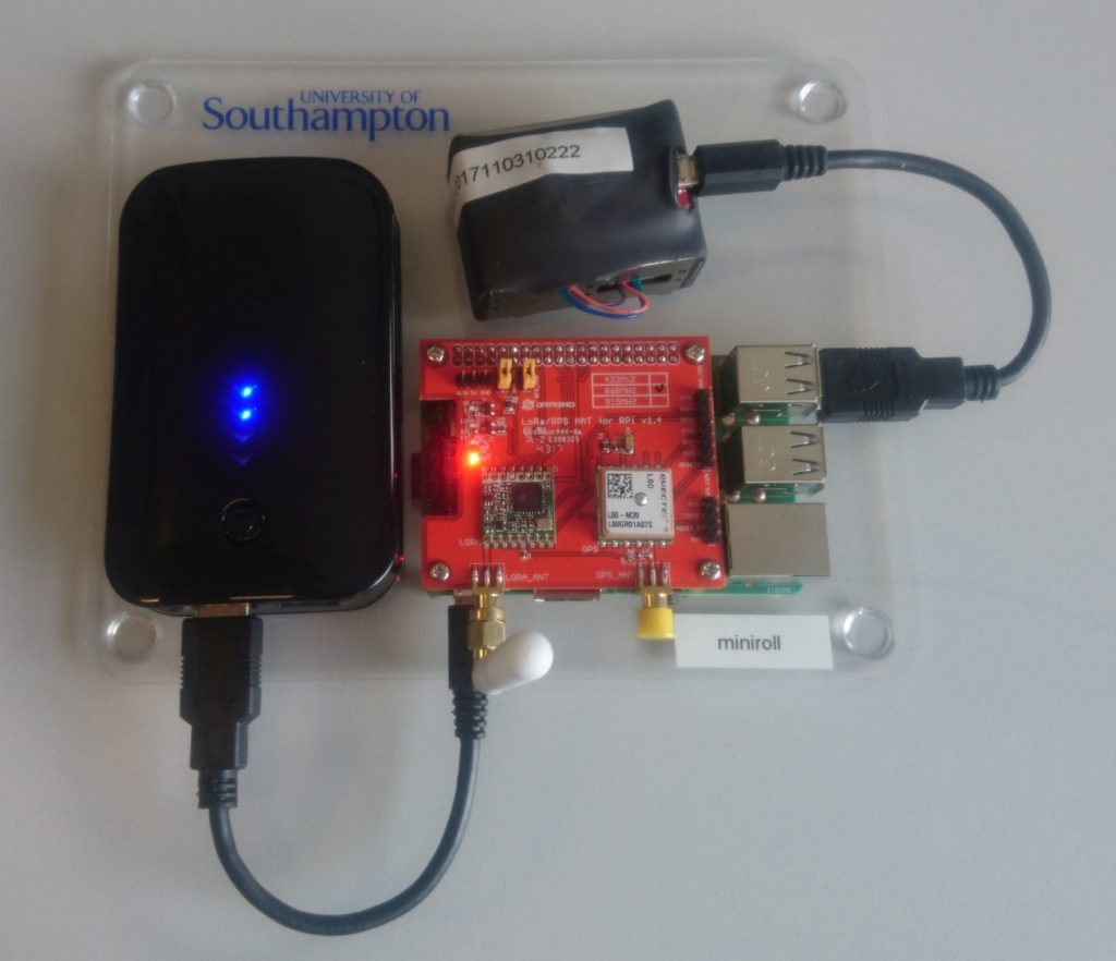
The links below are the suppliers we used to purchase the parts – other suppliers are available.
- Raspberry Pi (3B or 3B+) https://cpc.farnell.com/raspberry-pi/2773729/raspberry-pi-3-model-b/dp/SC14882
- SD card
- Plantower Particulate Matter Sensor https://www.ebay.co.uk/itm/PMS5003-G5-PlanTower-High-Precision-Laser-Dust-Sensor-Module-PM1-0-PM2-5-PM10/201903779518
- FTDI USB-serial http://www.hobbytronics.co.uk/ft232rl-breakout-2
- Dragino LoRaWAN HAT https://cpc.farnell.com/seeed-studio/113990254/gps-lora-hat-for-raspberry-pi/dp/SC14509?st=lora
- PiFace RTC (not used in workshop code but in the kits we provided) https://cpc.farnell.com/piface/shim-rtc/real-time-clock-for-raspberry/dp/SC13528
- Battery for RTC https://cpc.farnell.com/gp-batteries/gpca10/battery-lithium-3v-cr1220-1pk/dp/BT00449
- USB Power bank https://cpc.farnell.com/iconbit/ftb7800fx/powerbank-dual-usb-charger-7800mah/dp/BT06432
- 2 * USB cable https://uk.farnell.com/roline/11-02-8310/computer-cable-usb2-0-150mm-black/dp/2444222
- Velcro https://www.rapidonline.com/velcro-brand-vel-ec60236-stick-on-squares-25mm-x-24-sets-black-54-4297
We used heat shrink to attach the USB-serial adapter to the sensor as a single module. The heat shrink is not available in small quantities so a Velcro pad can be used instead to both secure the USB-serial adapter and to prevent accidental shorting of pins. The equipment was mounted on a custom laser cut perspex sheet, however, feel free to create your own mounting solution.
Software
We have written a couple of custom libraries to facilitate this workshop (which will be installed in the setup steps). If you want to dig deeper into the code it can be found on github. If you make any improvements to the code please submit a pull request.
- Draingo LoRaWAN HAT https://github.com/computenodes/dragino
- Cayenne LPP https://github.com/FEEprojects/cayennelpp-python
- Plantower interface https://github.com/FEEprojects/plantower
Setup
Having purchased / acquired the hardware the following steps have to be carried out to get to the stage where the workshop code can be run. In order for the LoRaWAN part to work you have to be in coverage of The Things Network. For the workshop we deployed 3 gateways on site. Coverage can be checked by using TTN Mapper. If you are not in coverage you can extend the network by running your own gateway. See https://www.thethingsnetwork.org/docs/gateways/ for details.
Hardware setup
In order to assemble the hardware do the following steps:
- Insert the battery into the RTC module.
- Attach the stand offs provided in the dragino LoRaWAN HAT box to the Rapsberry Pi.
- Place the RTC module on to the Pi header connections.
- Place the dragino LoRaWAN HAT on to the Pi and secure with the screws.
- Attach the antenna to the LORA_ANT connection on the dragino HAT.
- Solder the PM5003 to the USB-Serial, the important connections are (Pin 5) TX -> RX, (Pin 4)RX -> TX, (Pin 1)VCC -> 5V and (Pin 2)GND -> GND.
- Make sure the switch on the USB-Serial is set to 3V3.
- Connect the USB-serial to the Raspberry Pi using one of the micro-USB leads
Our finished nodes looked like
Software installation
Copy the latest Raspbian image on to the SD card, and then connect to the Pi and run the following script.
The code below will install the required libraries and software to run the workshop. This will take some time.
echo "dtparam=spi=on" | sudo tee -a /boot/config.txt
echo "dtoverlay=spi-gpio-cs" | sudo tee -a /boot/config.txt
echo "dtparam=i2c_arm=on" | sudo tee -a /boot/config.txt
sudo raspi-config noint do_serial 2

#get the spi CS pin overlay
wget https://github.com/computenodes/dragino/releases/download/v0.0.1/spi-gpio-cs.dtbo
sudo mv spi-gpio-cs.dtbo /boot/overlays/

#install jupyter
sudo apt update
sudo apt-get install -y python-dev
sudo -H pip install --upgrade pip
sudo -H pip install jupyter
sudo apt-get install -y python-seaborn python-pandas python3-pandas
sudo apt-get install -y ttf-bitstream-vera

sudo pip3 install jupyter
sudo ipython3 kernelspec install-self
jupyter notebook --generate-config
jupyter notebook password # this will prompt you for a password


#add jupyter to crontab
echo "@reboot pi /usr/local/bin/jupyter notebook --ip=0.0.0.0 --no-browser --notebook-dir=/home/pi >> /tmp/jupyter.out 2>> /tmp/jupyter.err" | sudo tee -a /etc/cron.d/jupyter

#setup the RTC
echo "i2c-bcm2708" | sudo tee -a /etc/modules
sudo modprobe i2c:mcp7941x
echo "@reboot root echo mcp7941x 0x6f > /sys/class/i2c-adapter/i2c-1/new_device; ( sleep 2; hwclock -s ) &" | sudo tee -a /etc/cron.d/rtc


#get the cayenne module
wget https://github.com/FEEprojects/cayennelpp-python/releases/download/v1.0.0/simplecayennelpp-1.0.0.tar.gz
#install it
pip3 install simplecayennelpp-1.0.0.tar.gz
#get the plantower module
wget https://github.com/FEEprojects/plantower/releases/download/v0.0.2/plantower-0.0.2.tar.gz
pip3 install plantower-0.0.2.tar.gz
#get the dragino lib and install
wget https://github.com/computenodes/dragino/releases/download/v0.0.2/dragino-0.0.2.tar.gz
pip3 install dragino-0.0.2.tar.gz
sudo reboot
Once the node has rebooted make sure it has the correct time (If it’s connected to a network it will do this automatically). Then run:
sudo hwclock -w
This sets the time on the hardware RTC so the Pi knows the time when it boots even without GPS or network connections.
The Things Network Setup
We use The Things Network to transfer the data from the device to Cayenne for viewing. This also requires setting up which can be done with the following steps. For more information please read The Things Network documentation.
- Register at The Things Network https://www.thethingsnetwork.org/.
- Create a new application
- On the integrations tab for the application add `Cayenne’.
- Register a device in the application. Make sure that it generates the `Device EUI’ and `App Key’.
- Edit the setting for the device to change `Activation Method’ to `ABP’. (You can use OTAA but for simplicity of the workshop we used ABP).
- Download an example config file for the dragino from https://raw.githubusercontent.com/computenodes/dragino/master/dragino.ini.default save it to `/home/pi/dragino.ini’
- Fill in the devadddr, nwskey, and appskey from The Things Network
Having done the above steps your config file should look similar but not identical to the following (The devaddr, nwskey and appskey lines will be different:
#GPS configuration
gps_baud_rate = 9600
gps_serial_port = "/dev/serial0"
gps_serial_timeout = 1
gps_wait_period = 10

#LoRaWAN configuration
spreading_factor = 7
max_power = "0x0F"
output_power = "0x0E"
sync_word = 0x34
rx_crc = True
#Where to store the frame count
fcount_filename = "/home/pi/.lora_fcount"

##Valid auth modes are ABP or OTAA
##All values are hex arrays eg devaddr = 0x01, 0x02, 0x03, 0x04
auth_mode = "abp"
devaddr = 0x26, 0x01, 0x19, 0xA9
nwskey = 0x4A, 0xE5, 0x3B, 0x8E, 0x1B, 0x4C, 0x24, 0x7C, 0x07, 0xA3, 0x52, 0x38, 0x3A, 0x28, 0x1F, 0xCD
appskey = 0x02, 0x1D, 0x25, 0xF1, 0x92, 0xCE, 0x2B, 0xA2, 0x89, 0x8F, 0x29, 0x18, 0x43, 0xA9, 0x00, 0x1E

#auth_mode = "otaa"
#deveui =
#appeui =
#appkey =
Cayenne Setup
In order to visualise the data you will also need an account on Cayenne https://cayenne.mydevices.com/cayenne/dashboard/start. Having created the account you need to add the device. To do this follow these steps:
- Click Add New… Device/Widget
- Select `LoRa from the list
- Select `The Things Network’ from the expanded list
- A new list now appears on the right, scroll down and select `Cayenne LPP’
- Copy the DevEUI from the things network and change the Name if you wish
- Click `Add device’.
Workshop Code
Finally we are at the point where we can write the code that was used in the workshop. Connect to the Jupyter notebook, the exact address for this will depend on your network but it may be available at http://raspberrypi:8888.
The code created is as follows:
from dragino import Dragino # import the module required for GPS and LoRaWAN
from simplecayennelpp import CayenneLPP # import the module required to pack the format cayenne expects
from plantower import Plantower # import the module to speak to the PM sensor
from time import sleep # import sleep so can wait between polling the sensor
sensor = Plantower()
dataList = []
for i in range(10):
    data = sensor.read()
    dataList.append(data.gr03um)
    sleep(1)
average_reading = sum(dataList) / len(dataList)

D = Dragino("/home/pi/dragino.ini") # Set up the dragino HAT
my_position = D.get_gps()
lpp = CayenneLPP()
lpp.addAnalogInput(1, round(average_reading))
lapp.addGPS(2, my_position.latitude, my_position.longitude, myposition.altitude)
D.send_bytes(list(lpp.getBuffer()))
If you find any mistakes in these instructions or they become out of date please comment below.
]]>Hardware
Having decided upon a standalone hardware based solution it was a matter of chosing which hardware to use. For another project we are using pycom devices; the LoPy in particular. This provides a LoRaWAN package in a convenient form factor which is programmed using Python. They also provide an expansion board the Pytrack which adds GPS connectivity to the board.
Having decided on the hardware we could then work out which of the other peripherals that the expansion board had to use. It was decided it would also be interesting to log GPS co-ordinates locally on the devices so that these could be compared to the data received at the base stations to identify gaps in coverage.
To build the hardware we used the following parts
Parts list
- LoPy
- Pytrack
- LoRaWAN antenna kit
- Pytrack case
- Battery
- Switch (Any SPST switch is suitable)
- JST connector for pytrack
- Contacts for pytrack JST connector
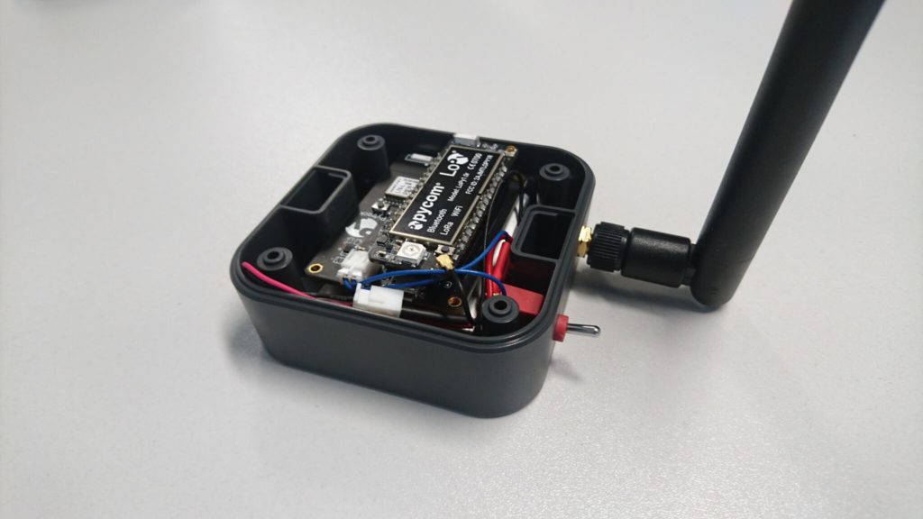
- Connector for battery (depends on battery used)
The battery is connected to via the switch to the pytrack PCB. This means the board can be turned on/off without having to open the case. The case still has to be opened to charge the battery as there is currently no external USB connector. There is also currently no way of viewing the debug LED when the case is closed. The battery and PCB are secured in place using velcro.
Software
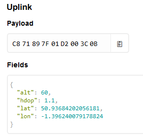
The easiest way for the data to be imported into TTN mapper is to use one of their standard formats. They accept simple ascii but recommend a more efficient binary encoding of the data. In order to check you have encoded the data correctly you can add a custom payload to the things network. This is provided in the comments in a git repo available at https://github.com/jpmeijers/RN2483-Arduino-Library/blob/master/examples/TheThingsUno-GPSshield-TTN-Mapper-binary/TheThingsUno-GPSshield-TTN-Mapper-binary.ino, but also reproduced below.
function Decoder(bytes, port) {
  var decoded = {};
  decoded.lat = ((bytes[0]<<16)>>>0) + ((bytes[1]<<8)>>>0) + bytes[2];
  decoded.lat = (decoded.lat / 16777215.0 * 180) - 90;
  decoded.lon = ((bytes[3]<<16)>>>0) + ((bytes[4]<<8)>>>0) + bytes[5];
  decoded.lon = (decoded.lon / 16777215.0 * 360) - 180;
  var altValue = ((bytes[6]<<8)>>>0) + bytes[7];
  var sign = bytes[6] & (1 << 7);
  if(sign){
    decoded.alt = 0xFFFF0000 | altValue;
  }else{
    decoded.alt = altValue;
  }
  decoded.hdop = bytes[8] / 10.0;
  return decoded;
}
Using this decoder has two advantages, you can see that the data you are sending makes sense and you verify that it is in the correct format to be understood by TTN Mapper.
The software for this is available from https://github.com/computenodes/pycom-gps-logger. It forms two parts, a part to run on the device. This was programmed using Visual Studio Code with the Pymakr plugin. Setup instructions are available from the pycom docs. Any details that are device specific are stored in config.py a default version is given in the repo and below. The correct details should be put in for your device.
APP_KEY = "" #Application key from the things network
APP_EUI = ""                 #The EUI for the app
JOIN_TIMEOUT = 0                             #passed to the LoRaWAN join function
GPS_TIMEOUT = 30                             #How long to wait for a GPS reading per attempt
POST_MESSAGE_SLEEP = 60 #How long to wait between messages - affects GPS sample rate when connected
GPS_READ_INTERVAL = 10  #How often to read the GPS if not on the LoRaWAN network
TTN mapper relies on getting latitude, longitude, altitude and HDOP. The default library that pycom provide for the pytrack only provides the latitude and the longitude, as the rest of the data is not provided in the particular NMEA string that they are parsing. However, consulting the datasheet for the GPS module showed that the module also produces
GPGGA
NMEA strings which do contain the required information. The provided library was therefore modified to include an additional function which provides the required information. This will be tested a bit more comprehensively before submitting a pull request to add this to the core library.
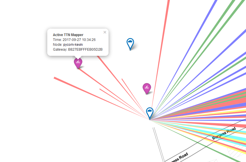
Once you have given the required details to TTN Mapper as per the FAQ you should see a purple marker appear which represents your mobile device, with coverage details being added to the map periodically. An example is shown below.
As well as submitting the data to TTN mapper we wanted to keep a record of the positions from the device for a forthcoming project in which we would need the raw data to compare again. In order to do this we have a python application which subscribes to an MQTT stream from the application and logs data into a monogodb store.
{
        "_id" : ObjectId("59c641d6c7a447dd52f8ba75"),
        "hdop" : 1,
        "timestamp" : "2017-09-23 11:13:26",
        "lon" : -1.39849,
        "alt" : 70,
        "gateways" : [
                {
                        "rssi" : -96,
                        "snr" : -1,
                        "gw_id" : "eui-b827ebfffee36ef8"
                },
                {
                        "rssi" : -102,
                        "snr" : 9,
                        "gw_id" : "eui-7276fffffe0102df"
                },
                {
                        "rssi" : -72,
                        "snr" : 9.8,
                        "gw_id" : "eui-b827ebfffeac4b12"
                },
                {
                        "rssi" : -104,
                        "snr" : 9,
                        "gw_id" : "eui-7276fffffe0103f0"
                },
                {
                        "rssi" : -106,
                        "snr" : 7,
                        "gw_id" : "eui-7276fffffe0103f0"
                },
                {
                        "rssi" : -122,
                        "snr" : -7,
                        "gw_id" : "eui-7276fffffe0103ec"
                },
                {
                        "rssi" : -99,
                        "snr" : 8,
                        "gw_id" : "eui-7276fffffe0103ec"
                }
        ],
        "lat" : 50.93727,
        "serial" : "70B3D5499247643E",
        "sf" : "SF7BW125"
}
Creating a GPS position logger for the LoRaWAN network has been an interesting task, and it has been very easy to iterate and add functionality. It is a very simple project to complete and it can be interesting seeing which base-stations are able to receive your signals.
]]>We had recently been looking at GPS receivers for another area of a project being worked on and decided to use the Adafruit Ultimate GPS. The reasons we liked the module were the fact it could take an external antenna, and it offers a PPS output. The external antenna is important because all our LoRaWAN base stations use metal enclosures. The PPS output means it can be used in place of the uBlox. The PPS (Pulse Per Second) output is a output pin from the GPS receiver which is used to signify the start of the second. By using a simple output rather than a character over a serial link a much higher accuracy can be achieved, as much less hardware processing is needed
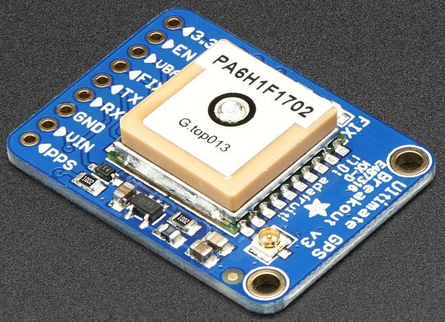
In order to connect this to the iC880 a standard 0.1″ header was soldered onto the GPS module. As this was just for testing the serial port is connected to the Raspberry Pi using a standard FTDI USB-serial converter cable. For the power, ground and PPS connectors our much abused Raspberry PI iC880A Lora Concentrator Gateway Shield has had some more patch wires soldered onto it, this time with sockets on the end to enable plugging into the 0.1″ header on the GPS module.
Software
    "gateway_conf": {
    "gateway_ID": "B827EBFFFEXXXXXX",
    "servers": [
        {
            "server_address": "router.eu.thethings.network",
            "serv_port_up": 1700,
            "serv_port_down": 1700,
            "serv_enabled": true
        }
    ],
    "gps_tty_path": "/dev/ttyUSB0",
    "contact_email": "test@example.com",
    "description": "GPS-test-node",
    "fake_gps": false,
    "forward_crc_valid": true,
    "forward_crc_error": false,
    "forward_crc_disabled": true
    }
}
The local config is very similar to that used for the uBlox module the only change is the serial port being used.
Testing
As before testing had to wait until with weather co-operated. When started up the program went through the same steps as seen last time waiting for the GPS receiver to send the correct data through before using it for a lock. This is still attempting to send beacons out, however this time it is succeeding. Although this could be because it’s connected to a different concentrator board.
NOTE: [down] beacon ready to send (frequency 0 Hz)
--- Beacon payload ---
0xEE - 0xFF - 0xC0 - 0x00 - 0x00 - 0x00 - 0x00 - 0x84
0x00 - 0x00 - 0x9F - 0x91 - 0x59 - 0x38 - 0x0E - 0x1C
0x8C - 0x00 - 0x00 - 0x00 - 0x00 - 0x00 - 0x00 - 0x00
--- end of payload ---
NOTE: [down] beacon sent successfully
I am still confused as to why it is sending out beacons given it again clearly says
INFO: Beacon is disabled
Maybe I’m misunderstanding what this configuration option means.
At the moment we have just tested that the gateways are getting the time / position from the GPS receiver, we are not doing anything more advanced with it. That will come in time, and updates will be posted.
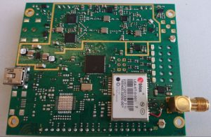
]]>The iC880A is a popular PCB for creating a multichannel LoRaWAN base station. It is supplied with pads for the addition of a u-blox LEA-6T. As well as adding the GPS receiver module several other components have to be added including a power supply, USB connector and associated passives / TVS protection diodes.
|
|
|
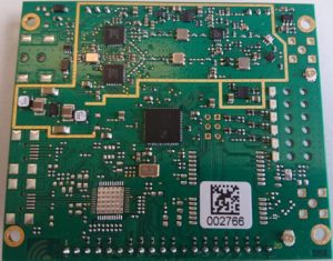
However, following the instructions provided produces a system that enable communication with the GPS receiver but is unable to receive any satellite signal. This is due to a couple of problems, in order to debug these the Hardware Integration Manual for the LEA-6T is needed.
The first stage of the debugging was to identify that the active antenna connected to the SMA was not receiving power. Whilst debugging this stage it was confirmed it was an aerial problem as when probing for DC voltage on the antenna connector the multi-meter probes were acting as antenna enabling signal to be received and a lock to be obtained.
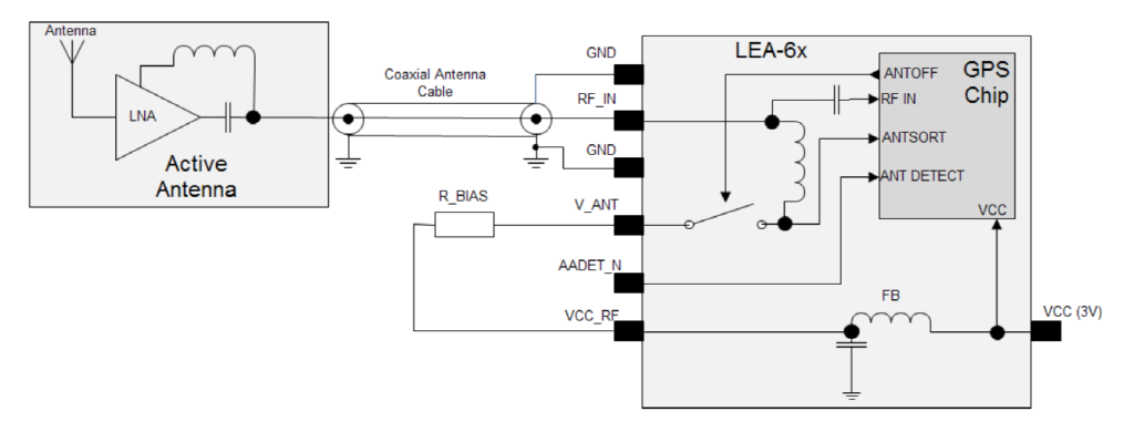
The first problem is in the power supply circuit for the active antenna. R_BIAS (R959) is the recommended 10 Ohms, however, there also appears to be R958 connected to the V_ANT pin. R958 is a 0 Ohm resistor to ground meaning V_ANT is now tied to 0V and therefore unable to power the active antenna. Upon removal of R958, it was possible to observe 3V at the RF pin suitable for powering an LNA as part of the antenna. However, the antenna was still receiving satellite signals.
This led to the diagnosis of a further problem the instructions from IMST have a IC (U950) between RF_IN on the receiver and the SMA connector on the PCB. This component is a SF1186K-3, which is a SAW Filter, which is designed to only pass the required frequency, thus improving noise rejection. This, chip also blocks DC (Minimum 35dB rejection) meaning the antenna does not receive power. As can be seen from the integration manual, the receiver does not require this filter, so it was remove and bypassed (visible in the bottom right of the second photo). Having completed this modification the GPS receiver is now able to receive the satellite signal and get a position lock. This was tested using the u-centre software available from u-blox connected via USB.
Finally the GPS serial output is connected to the Pi onboard serial port. This can either be done using jumper leads. For development we are using the Raspberry PI iC880A Lora Concentrator Gateway Shield, however, this doesn’t have these ports connected, so patch wire was used to connect the required pins.
Software Setup
Now the GPS is able to communicate both with the Pi and satellites a bit of software configuration is needed. The Pi is now connected to UART1 of the GPS receiver needs configuration. This can be done in u-centre, view -> configuration). Before leaving a page you need to click send to actually tell the GPS unit about the change.
The first things is to enable NMEA output on the serial port connected to the Pi. This is under the ‘PRT’ section. UART1 should be set to NMEA out @ baudrate 9600.
The GPS module is now sending lots of NMEA messages to the Pi, most of which are ignored by the LoRa gateway. The only messages that the code parses match $G?RMC & $G?GGA. All other messages can be turned off using the ‘MSG’ section of the configuration.
Having made the changes to the configuration these need to be made persistent. Go to ‘CFG’, make sure “save current configuration” is selected and then click send. These changes should now persist.
Make sure that the serial port is enabled on the Rapsberry Pi using raspi-config. Do not enable a console on the serial port.
Finally change the local_config.json to enable the GPS receiver. The configuration used on the node used for testing is
    "gateway_conf": {
    "gateway_ID": "B827EBFFFEXXXXXX",
    "servers": [
        {
            "server_address": "router.eu.thethings.network",
            "serv_port_up": 1700,
            "serv_port_down": 1700,
            "serv_enabled": true
        }
    ],
    "gps_tty_path": "/dev/serial0",
    "contact_email": "test@example.com",
    "description": "GPS-test-node",
    "fake_gps": false,
    "forward_crc_valid": true,
    "forward_crc_error": false,
    "forward_crc_disabled": true
    }
}
Testing
Due to the poor quality of GPS signal available in my office and in the (basement) electronics lab testing has had to wait until the weather has been good enough to spend some time outside. This has meant waiting rather longer than hoped, but that’s the British weather for you! When suitable weather did arrive I took the gateway and a client device outside and setup on a picnic bench outside the office. On starting the poly_pkt_fwd script there was the usual output stream with some additional lines shown below.
INFO: Validation thread activated.
WARNING: [gps] GPS out of sync, keeping previous time reference
WARNING: [gps] GPS out of sync, keeping previous time reference
INFO: [down] for server router.eu.thethings.network PULL_ACK received in 299 ms
INFO: [down] for server router.eu.thethings.network PULL_ACK received in 82 ms
INFO: [down] for server router.eu.thethings.network PULL_ACK received in 93 ms

##### 2017-08-01 17:06:10 GMT #####
### [UPSTREAM] ###
# RF packets received by concentrator: 0
# CRC_OK: 0.00%, CRC_FAIL: 0.00%, NO_CRC: 0.00%
# RF packets forwarded: 0 (0 bytes)
# PUSH_DATA datagrams sent: 0 (0 bytes)
# PUSH_DATA acknowledged: 0.00%
### [DOWNSTREAM] ###
# PULL_DATA sent: 3 (100.00% acknowledged)
# PULL_RESP(onse) datagrams received: 0 (0 bytes)
# RF packets sent to concentrator: 0 (0 bytes)
# TX errors: 0
### [GPS] ###
# Valid gps time reference (age: 1 sec)
# System GPS coordinates: latitude 50.93680, longitude -1.40584, altitude 69 m
##### END #####
As can be seen at first start up the GPS receiver hadn’t yet got a decent lock so the forwarder ignore the data that it was receiving from the device and kept going with the time the device had from NTP. Shortly afterwards it can be seen that the GPS had achieved a lock and was being used as the time reference.
I am confused by one aspect of the behaviour of the system, and that is the transmission of beacons. In the global_conf file the transmission of beacons is disabled. This is confirmed by the following line in the logs.
INFO: Beacon is disabled
However, it would appear that the device still tries to send a beacon.
NOTE: [down] beacon ready to send (frequency 0 Hz)
--- Beacon payload ---
0xEE - 0xFF - 0xC0 - 0x00 - 0x00 - 0x00 - 0x00 - 0x84
0x00 - 0x80 - 0xA1 - 0x91 - 0x59 - 0x38 - 0x0E - 0x1C
0x8C - 0x00 - 0x00 - 0x00 - 0x00 - 0x00 - 0x00 - 0x00
--- end of payload ---
WARNING: [down] beacon was scheduled but failed to TX
Further testing was carried out and it was identified that the PPS output of the u-blox module was not actually connected to the PPS line used by the transceiver (and available on the header). The failure of transmission was because the expected rising edge never arrived rather than anything with the actual transmission going wrong. On the iC880A PCB there is a test pad available by the timepulse output of the u-blox module. So it was a simple matter of linking the two together. Having done this it was tested again and it worked giving the following output when transmitting a beacon.
NOTE: [down] beacon ready to send (frequency 0 Hz)
--- Beacon payload ---
0xEE - 0xFF - 0xC0 - 0x00 - 0x00 - 0x00 - 0x00 - 0x84
0x00 - 0x80 - 0x62 - 0x94 - 0x59 - 0x38 - 0x0E - 0x1C
0x8C - 0x00 - 0x00 - 0x00 - 0x00 - 0x00 - 0x00 - 0x00
--- end of payload ---
NOTE: [down] beacon sent successfully
Although why it is transmitting a beacon with the flag set to false is still a mystery to me.
I’m lucky in that I have experience working with 0402 components which meant soldering on the passives was a feasbile proposition, and the uBlox module itself is a reasonable size for hand soldering. However, the SAW filter was beyond my abilities (many thanks to my colleague Graeme Bragg for his help with this.) so the fact it is not needed reduces the complexity of this modification considerably. Even so it’s not something I would recommend people without experience of hand soldering 0402 components tries. Which got us thinking there must be an easier way to add GPS receivers onto this iC880A concentrator boards. More to follow.
]]>
More powerful message brokers are capable of sorting messages based on their properties. Different messages may need to be delivered to entirely different devices on a network. RabbitMQ allows for the sorting of different types of messages based on their properties, ensuring they go straight to the correct delivery point.

There are many ways in which RabbitMQ can be instructed to distribute messages. For example, in a “fanout” exchange every message received can be sent to every known consumer. It is capable of sorting messages based on their content.
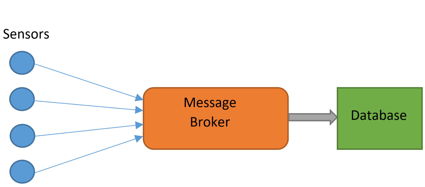
In our deployment, RabbitMQ was to be used to take messages from The Things Network gatweays and store them. MQTT (Message Queue Telemetry Transport) is a protocol designed for machine-to-machine (Internet of Things) applications, and was the protocol used with RabbitMQ. It may be necessary to enable the MQTT plugin:
RABBITMQ-PLUGINS ENABLE RABBITMQ_MQTT
RabbitMQ can be interacted with using a multitude of different programming languages; we used Python. Messages from the gateways were correctly received by RabbitMQ, however it was not possible to process them further. The complexity of RabbitMQ made it difficult to perform any processes more complex than sending and receiving messages from the localhost. After many hours of tweaking, it was still not possible to obtain data via RabbitMQ, and an alternative solution was necessary.
Mosquitto is an alternative message broker, developed exclusively for use with MQTT. It is a much simpler, lightweight alternative to RabbitMQ. Due to its reduced feature set, performing complex routing arrangements is less practical. RabbitMQ also features a slick, built in user interface, viewable through a web browser, a luxury not available on the Mosquitto broker. This makes it less easy understand the status of the message broker and the data. This simplicity was an advantage however; shortly after installing and switching to Mosquitto, data was correctly received. Furthermore, it is often possible to process and sort the messages in Python (or another language), negating an advantage of RabbitMQ
When choosing a message broker, it is important to evaluate whether the extra features of RabbitMQ are really necessary, and justify the extra complexity. In our use case the goal was simply to transfer data from The Things Network to be stored in MongoDB. It was far quicker and more efficient to use MQTT than RabbitMQ, and there was no loss in functionality in doing so.
Pika (RabbitMQ-Python Interface)/
Paho MQTT (Python MQTT client)
import paho.mqtt.client as mqtt  # library for communicating with mqtt
from pymongo import MongoClient  # mongoDB library
import json  # for (de)serialising javascript objects


def TTN_add():
    try:
        print("TTN_Add running")
        mqclient = mqtt.Client()
        mqclient.on_connect = on_connect  # on connection runs "on_connect function"
        mqclient.on_message = on_message  # on message...
        mqclient.connect("localhost", 1883, 60)  # 60 indicates keep-alive time
        mqclient.loop_forever()  # keeps it going forever
    except KeyboardInterrupt:
        mqclient.loop_stop()
        print("stopped")


def mongo_insert(Gateway_ID, payload):  # function to add stuff to the database
    collection = db.test_collection  # this creates the collection
    print ("Gateway_ID " + Gateway_ID)
    payload = json.loads(payload)  # payload to json version
    collection.insert_one(payload)
    return


def on_connect(mqclient, userdata, flags, rc):
    print("Connected with result code "+str(rc))
    mqclient.subscribe("gateway/#")  # only gateway topics


def on_message(mqclient, userdata, msg):
    print("on_message")
    print (msg.topic, msg.payload)
    # print (type(msg.payload))
    mongo_insert(msg.topic, msg.payload)


moclient = MongoClient('localhost', 27017)
db = moclient.ttn_database
TTN_add() #starts event handlers
]]>