pip install plantower
The pypi module page can be found at https://pypi.org/project/plantower/
]]>Air quality and low-cost sensors
Some of the slides presented at the beginning of the workshop were infographics taken from the World Health Organization (WHO). They can be found along with other general figures about air quality in the world at http://www.who.int/airpollution/infographics/en/. If you want to learn more about air quality and especially about air quality in UK, we suggest you to read the report published by the Royal College of Physicians and the Royal College of Paediatrics and Child Health in 2016: Every breath we take: the lifelong impact of air pollution.
The sensors used during the workshop are low-cost sensors used to monitor fine particles (PM10 and PM2.5). We strongly encourage you to read the advice from the Department for Environment Food & Rural Affairs (DEFRA) on the use of low-cost sensors for air pollution to have a better understanding of their limitations. The recommendation can be found at https://uk-air.defra.gov.uk/library/aqeg/pollution-sensors.php
Hardware
The links below are the suppliers we used to purchase the parts – other suppliers are available.
- Raspberry Pi (3B or 3B+) https://cpc.farnell.com/raspberry-pi/2773729/raspberry-pi-3-model-b/dp/SC14882
- SD card
- Plantower Particulate Matter Sensor https://www.ebay.co.uk/itm/PMS5003-G5-PlanTower-High-Precision-Laser-Dust-Sensor-Module-PM1-0-PM2-5-PM10/201903779518
- FTDI USB-serial http://www.hobbytronics.co.uk/ft232rl-breakout-2
- Dragino LoRaWAN HAT https://cpc.farnell.com/seeed-studio/113990254/gps-lora-hat-for-raspberry-pi/dp/SC14509?st=lora
- PiFace RTC (not used in workshop code but in the kits we provided) https://cpc.farnell.com/piface/shim-rtc/real-time-clock-for-raspberry/dp/SC13528
- Battery for RTC https://cpc.farnell.com/gp-batteries/gpca10/battery-lithium-3v-cr1220-1pk/dp/BT00449
- USB Power bank https://cpc.farnell.com/iconbit/ftb7800fx/powerbank-dual-usb-charger-7800mah/dp/BT06432
- 2 * USB cable https://uk.farnell.com/roline/11-02-8310/computer-cable-usb2-0-150mm-black/dp/2444222
- Velcro https://www.rapidonline.com/velcro-brand-vel-ec60236-stick-on-squares-25mm-x-24-sets-black-54-4297
We used heat shrink to attach the USB-serial adapter to the sensor as a single module. The heat shrink is not available in small quantities so a Velcro pad can be used instead to both secure the USB-serial adapter and to prevent accidental shorting of pins. The equipment was mounted on a custom laser cut perspex sheet, however, feel free to create your own mounting solution.
Software
We have written a couple of custom libraries to facilitate this workshop (which will be installed in the setup steps). If you want to dig deeper into the code it can be found on github. If you make any improvements to the code please submit a pull request.
- Draingo LoRaWAN HAT https://github.com/computenodes/dragino
- Cayenne LPP https://github.com/FEEprojects/cayennelpp-python
- Plantower interface https://github.com/FEEprojects/plantower
Setup
Having purchased / acquired the hardware the following steps have to be carried out to get to the stage where the workshop code can be run. In order for the LoRaWAN part to work you have to be in coverage of The Things Network. For the workshop we deployed 3 gateways on site. Coverage can be checked by using TTN Mapper. If you are not in coverage you can extend the network by running your own gateway. See https://www.thethingsnetwork.org/docs/gateways/ for details.
Hardware setup
In order to assemble the hardware do the following steps:
- Insert the battery into the RTC module.
- Attach the stand offs provided in the dragino LoRaWAN HAT box to the Rapsberry Pi.
- Place the RTC module on to the Pi header connections.
- Place the dragino LoRaWAN HAT on to the Pi and secure with the screws.
- Attach the antenna to the LORA_ANT connection on the dragino HAT.
- Solder the PM5003 to the USB-Serial, the important connections are (Pin 5) TX -> RX, (Pin 4)RX -> TX, (Pin 1)VCC -> 5V and (Pin 2)GND -> GND.
- Make sure the switch on the USB-Serial is set to 3V3.
- Connect the USB-serial to the Raspberry Pi using one of the micro-USB leads
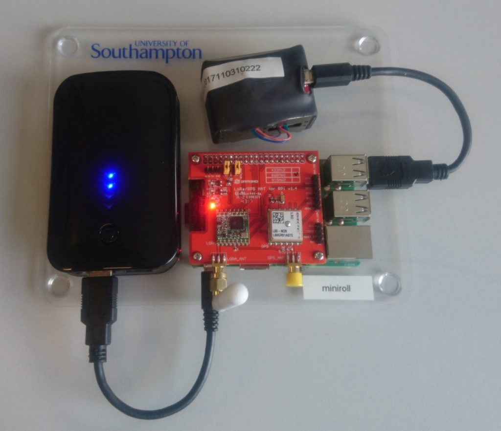
Our finished nodes looked like
Software installation
Copy the latest Raspbian image on to the SD card, and then connect to the Pi and run the following script.
The code below will install the required libraries and software to run the workshop. This will take some time.
echo "dtparam=spi=on" | sudo tee -a /boot/config.txt
echo "dtoverlay=spi-gpio-cs" | sudo tee -a /boot/config.txt
echo "dtparam=i2c_arm=on" | sudo tee -a /boot/config.txt
sudo raspi-config noint do_serial 2

#get the spi CS pin overlay
wget https://github.com/computenodes/dragino/releases/download/v0.0.1/spi-gpio-cs.dtbo
sudo mv spi-gpio-cs.dtbo /boot/overlays/

#install jupyter
sudo apt update
sudo apt-get install -y python-dev
sudo -H pip install --upgrade pip
sudo -H pip install jupyter
sudo apt-get install -y python-seaborn python-pandas python3-pandas
sudo apt-get install -y ttf-bitstream-vera

sudo pip3 install jupyter
sudo ipython3 kernelspec install-self
jupyter notebook --generate-config
jupyter notebook password # this will prompt you for a password


#add jupyter to crontab
echo "@reboot pi /usr/local/bin/jupyter notebook --ip=0.0.0.0 --no-browser --notebook-dir=/home/pi >> /tmp/jupyter.out 2>> /tmp/jupyter.err" | sudo tee -a /etc/cron.d/jupyter

#setup the RTC
echo "i2c-bcm2708" | sudo tee -a /etc/modules
sudo modprobe i2c:mcp7941x
echo "@reboot root echo mcp7941x 0x6f > /sys/class/i2c-adapter/i2c-1/new_device; ( sleep 2; hwclock -s ) &" | sudo tee -a /etc/cron.d/rtc


#get the cayenne module
wget https://github.com/FEEprojects/cayennelpp-python/releases/download/v1.0.0/simplecayennelpp-1.0.0.tar.gz
#install it
pip3 install simplecayennelpp-1.0.0.tar.gz
#get the plantower module
wget https://github.com/FEEprojects/plantower/releases/download/v0.0.2/plantower-0.0.2.tar.gz
pip3 install plantower-0.0.2.tar.gz
#get the dragino lib and install
wget https://github.com/computenodes/dragino/releases/download/v0.0.2/dragino-0.0.2.tar.gz
pip3 install dragino-0.0.2.tar.gz
sudo reboot
Once the node has rebooted make sure it has the correct time (If it’s connected to a network it will do this automatically). Then run:
sudo hwclock -w
This sets the time on the hardware RTC so the Pi knows the time when it boots even without GPS or network connections.
The Things Network Setup
We use The Things Network to transfer the data from the device to Cayenne for viewing. This also requires setting up which can be done with the following steps. For more information please read The Things Network documentation.
- Register at The Things Network https://www.thethingsnetwork.org/.
- Create a new application
- On the integrations tab for the application add `Cayenne’.
- Register a device in the application. Make sure that it generates the `Device EUI’ and `App Key’.
- Edit the setting for the device to change `Activation Method’ to `ABP’. (You can use OTAA but for simplicity of the workshop we used ABP).
- Download an example config file for the dragino from https://raw.githubusercontent.com/computenodes/dragino/master/dragino.ini.default save it to `/home/pi/dragino.ini’
- Fill in the devadddr, nwskey, and appskey from The Things Network
Having done the above steps your config file should look similar but not identical to the following (The devaddr, nwskey and appskey lines will be different:
#GPS configuration
gps_baud_rate = 9600
gps_serial_port = "/dev/serial0"
gps_serial_timeout = 1
gps_wait_period = 10

#LoRaWAN configuration
spreading_factor = 7
max_power = "0x0F"
output_power = "0x0E"
sync_word = 0x34
rx_crc = True
#Where to store the frame count
fcount_filename = "/home/pi/.lora_fcount"

##Valid auth modes are ABP or OTAA
##All values are hex arrays eg devaddr = 0x01, 0x02, 0x03, 0x04
auth_mode = "abp"
devaddr = 0x26, 0x01, 0x19, 0xA9
nwskey = 0x4A, 0xE5, 0x3B, 0x8E, 0x1B, 0x4C, 0x24, 0x7C, 0x07, 0xA3, 0x52, 0x38, 0x3A, 0x28, 0x1F, 0xCD
appskey = 0x02, 0x1D, 0x25, 0xF1, 0x92, 0xCE, 0x2B, 0xA2, 0x89, 0x8F, 0x29, 0x18, 0x43, 0xA9, 0x00, 0x1E

#auth_mode = "otaa"
#deveui =
#appeui =
#appkey =
Cayenne Setup
In order to visualise the data you will also need an account on Cayenne https://cayenne.mydevices.com/cayenne/dashboard/start. Having created the account you need to add the device. To do this follow these steps:
- Click Add New… Device/Widget
- Select `LoRa from the list
- Select `The Things Network’ from the expanded list
- A new list now appears on the right, scroll down and select `Cayenne LPP’
- Copy the DevEUI from the things network and change the Name if you wish
- Click `Add device’.
Workshop Code
Finally we are at the point where we can write the code that was used in the workshop. Connect to the Jupyter notebook, the exact address for this will depend on your network but it may be available at http://raspberrypi:8888.
The code created is as follows:
from dragino import Dragino # import the module required for GPS and LoRaWAN
from simplecayennelpp import CayenneLPP # import the module required to pack the format cayenne expects
from plantower import Plantower # import the module to speak to the PM sensor
from time import sleep # import sleep so can wait between polling the sensor
sensor = Plantower()
dataList = []
for i in range(10):
    data = sensor.read()
    dataList.append(data.gr03um)
    sleep(1)
average_reading = sum(dataList) / len(dataList)

D = Dragino("/home/pi/dragino.ini") # Set up the dragino HAT
my_position = D.get_gps()
lpp = CayenneLPP()
lpp.addAnalogInput(1, round(average_reading))
lapp.addGPS(2, my_position.latitude, my_position.longitude, myposition.altitude)
D.send_bytes(list(lpp.getBuffer()))
If you find any mistakes in these instructions or they become out of date please comment below.
]]>The K30 is a low-cost, low-maintenance CO2 sensor capable of interfacing with a Raspberry Pi. It is designed to accurately measure ambient CO2 levels over long periods of time. The K30 detects CO2 using an infrared source, and an infrared detector. Since different molecules absorb different wavelengths of infrared light, the amount of absorption at certain wavelengths indicates the levels of those molecules. This leads to measurement issues when other molecules absorb light at similar wavelengths. In situations of low concentrations, SO2 and NO2 can cause cross sensitivity with CO2.
Used in conjunction with a Raspberry Pi, the K30 is perfect for remote monitoring of CO2 levels. The Raspberry Pi has many unique qualities that make it perfect for interfacing with the K30 and other sensors. Its respectable compute power, versatile General Purpose Input Output (GPIO) pins, and full network capabilities allow it work with almost any sensor. Combined with its low cost and compact size, it is an excellent choice for most applications. The Raspberry Pi 3 has Wi-Fi and Bluetooth built in which makes sending the data to other devices relatively easy. In our deployment of the K30, remote data communication will achieved using LoRaWAN, a long range, low power network. This will be used to send data to a gateway connected to the internet.
Some setup is required to best utilise the Raspberry Pi to communicate with the K30 Sensor. The K30 communicates over serial, which required the Raspberry Pi to have UART (Universal Asynchronous Receiver Transmitter) enabled. This can be done by editing the boot configuration:
$ sudo nano /boot/config.txt
And appending the file with:
enable_uart=1
By default, the console uses the serial output to output data, which can be used as a way to control the computer headlessly. This should be disabled to allow the serial output to be used by the K30 for data transmission. This can be done by deleting the console serial port allocation in the boot file:
$ sudo nano /boot/config.txt
The allocation will look something like:
“console=ttyAMA0,115200”
Alternatively, this can be disabled through the interface options in the raspberry configuration menu:
sudo raspi-config
Once the Pi is prepared to receive serial data, the K30 must be connected. This is a relatively simple case of connecting the K30 to 5v (a separate power supply was used), connecting the Pi and K30 to ground, and then cross-connecting the serial connections. A simple LED circuit was also established from the Pi’s GPIOs.
To test the K30 sensor, a prototype as developed, using a Raspberry Pi, the sensor, and some LEDs. CO2 readings were read from the K30 using the serial library in Python, which then controlled LEDS via the GPIOs. To visually demonstrate the functionality of the K30, a red LED was turned on when values over 1000 ppm of CO2 were detected. Values within the room were typically around 600 ppm, which could easily be raised over the 1000 ppm threshold by exhaling on the sensor. The ambient readings are in line with the expected CO2 levels for an office, and the sensor clearly respond to an increase in CO2 levels.
The full Python code used is below. Note that the serial port is TTYSO which is standard for the Raspberry Pi model 3. In earlier versions of the Raspberry Pi this may be different.
More information on the K30: https://www.co2meter.com/products/k-30-co2-sensor-module
Full Python code:
#rpi serial connections
#Python app to run a K-30 Sensor
import serial
import time
import RPi.GPIO as GPIO
GPIO.setmode(GPIO.BOARD)
GPIO.setup(12, GPIO.OUT)
GPIO.setup(16, GPIO.OUT)
ser = serial.Serial("/dev/ttyS0", baudrate=9600, timeout = 1) #serial port may vary from pi to pi
print ("AN-137: Raspberry Pi3 to K-30 Via UART\n")
ser.flushInput()
time.sleep(1)
cutoff_ppm = 1000 #readings above this will cause the led to turn red

for i in range(1,101):
    ser.flushInput()
    ser.write("\xFE\x44\x00\x08\x02\x9F\x25")
    time.sleep(.5)
    resp = ser.read(7)
    #print (type(resp)) #used for testing and debugging
    #print (len(resp))
    #print (resp)
    #print ("this is resp" + resp)
    high = ord(resp[3])
    low = ord(resp[4])
    print(high)
    print(low)
    co2 = (high*256) + low
    print ("i = ",i, " CO2 = " +str(co2))
    GPIO.output(12, GPIO.LOW)
    GPIO.output(16, GPIO.LOW)

    if co2 > cutoff_ppm:
        GPIO.output(12, GPIO.HIGH)
    else:
        GPIO.output(16, GPIO.HIGH)
    time.sleep(.1)

]]>