|
3.4. Event Related Potentials Results:
3.4.1. The eye movement:
Figure (3.4.1.) shows the averaged of the eye movement potentials and shows that these are negligible. Recordings were all scanned for eye movements and individual sweeps containing blinks were rejected. In this work, eye movements made a negligible contribution and other trace are not shown.
A series of positive and negative components occurred in the all groups’ traces for the learners and non-learners with all task-recording conditions. We found that the pre-stimulus baselines of the waveforms are very similar, and the sensory portions of the waveforms are similar too in all groups (Figure 3.4.2.).

Figure (3.4.1.) shows the grand averaged EOG after rejection of all blinking and eye-movements artefact at HEOG and VEOG representing the horizontal and vertical eye-movement monitor electrodes respectively
3.4.2. Pattern differences:
The complementary pattern used as stimuli, although forming two categories, was very similar visually. This showed in sensory VEP, and the cognitive portion of the traces, the morphology and the latency of ERPs elicited and evoked by either patterns (image type A and image type B) are similar for the both groups (learners and non-learners) pre-stimulus and post-stimulus from the beginning to the end of the task. There were no statistical significant differences figure (3.4.3.) 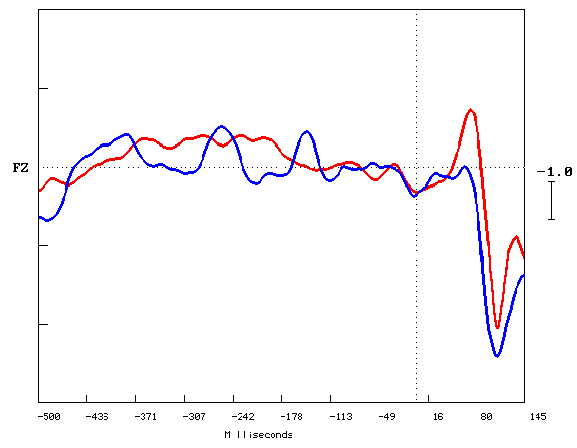
Figure (3.4.2.) shows Zoom grand average ERP waveform elicited by all answers trials for learners in red color trace and non-learners in blue color trace, at FZ site electrode. Y-axis shows amplitude in Microvolts (
m n ), and X-axis shows latency in milliseconds (msec). The black vertical dotted line marks the point of stimulus onset, and the horizontal black dotted line represents the baseline. Upward deflection represents the negativity.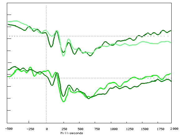
Figure (3.4.3.) shows the grand averaged ERPs elicited by the images type A trial traces in dark green and the images type B trials traces in light green color. The non-learners represented by the top traces and the learners represented by the bottom traces. Recorded from mid-frontal site electrode at FZ, during the learning task. Y-axis shows amplitude in Microvolts (
m n ), and X-axis shows latency in milliseconds (ms). The black vertical dotted line marks the point of stimulus onset, and the horizontal black dotted line represents the baseline. Upward deflection represents the negativity.The positive going activity can be called P300 but there is no clear peak. P300 peaks most probably between 300msec and 800msec so it is difficult to see the exact location of it in this graph, but we can see a definite increase in the positivity this time span. Traces begin to change at 250msec and show marked differences from 300msec to 800msec (Figures for fz’s ERPs).
Two time windows were chosen to compare between the groups and the subgroups, and were chosen because they encompassed much of the learners and non-learners difference evident in the grand averaged waveform. The first time window is (250msec - 500msec) and the second time window is (500msec - 800msec).
This increased positivity from about 250msec latency and beyond (P3a or P3b) during a learning task for the learners and non-learners correlate with our hypothesis that there is a difference in brain activity as a result of trying to learn.
3.3.3. The learners and non-learners ERPs:
Figure (3.4.4.) shows the superimposed grand average (-500msec to 2000msec) ERPs elicited by subject’s performance for the learners in red color traces after in all experimental groups during the last fifty trials of the learning task and the observers in black color trace. Recorded from mid-frontal site electrode (FZ). The trace morphology was very similar from 500msec pre-stimulus to 200msec post-stimulus. The observers trace back to the baseline to the end of the task. There were many peaks positive and negative in every group trace, the learners trace for group (FR) showed two more positive peaks than the other groups traces with differences of the peak latencies at 350msec and 590msec. The learners in peaks at 450msec and 650msec. The learners of group (Lfr) peaks at 440msec and at 690msec. Group (LfR) positive peaks at 500msec and 720msec.
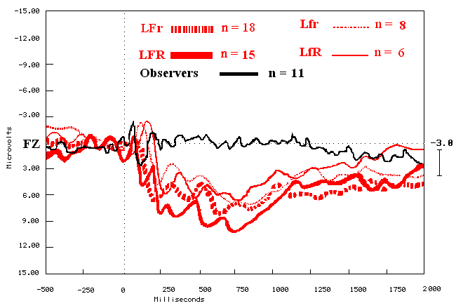
Figure (3.4.4.) shows the grand average ERPs elicited by subject's performance for the learners in red color traces after in all experiments groups during the last fifty trials of the learning task and the observers in black color trace. Recorded from mid-frontal site electrode (FZ), Y-axis shows amplitude in Microvolts (
m n ), and X-axis shows latency in milliseconds (msec). The black vertical dotted line marks the point of stimulus onset, and the horizontal black dotted line represents the baseline. Upward deflection represents the negativity.Figure (3.4.5.) shows the superimposed grand average (-500msec to 2000msec) ERPs elicited by subject’s performance for the non-learners in blue color traces after in all experiments groups during the last fifty trials of the learning task and the observers in black color trace. Recorded from mid-frontal site electrode (FZ). The trace morphology was very similar from 500msec pre-stimulus to 200msec post-stimulus. The observers' trace returns back to the baseline to the end of the task. There were many peaks positive and negative in every group trace, but the positive peaks were not the same amplitude when compared with the learners as shown in (figure 3.4.4.). The non-learners traces showed very clear positive peak at 300 msec for group I (nLFr) and group IV (nLfR), and at 350msec for group III (nLfr). There were more positive and negatives peaks but not strong like the early ones.
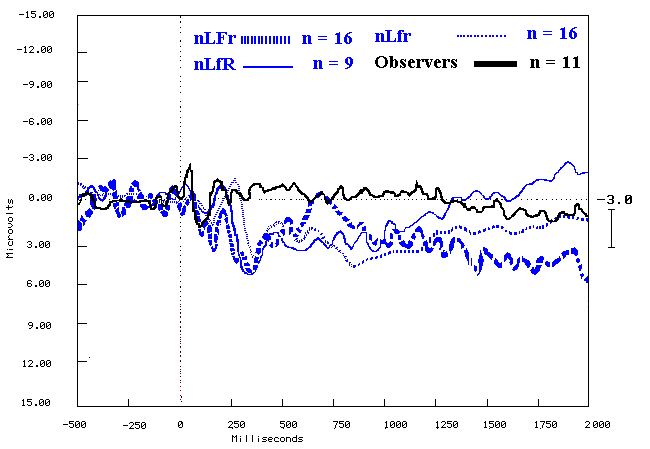
Figure (3.4.5.) shows the grand average ERPs elicited by subject's performance for the non-learners in blue color traces after in all experiments groups during the last fifty trials of the learning task and the observers in black color trace. Recorded from mid-frontal site electrode (FZ), Y-axis shows amplitude in Microvolts (
m n ), and X-axis shows latency in milliseconds (msec). The black vertical dotted line marks the point of stimulus onset, and the horizontal black dotted line represents the baseline. Upward deflection represents the negativity.The learners mean amplitudes were compared to the non-learners mean amplitudes during the last quartile group by using repeated measures two ways ANOVA (Learners & non-learners) X all electrodes Locations (Loc.). The results revealed that there were statistically significant differences in all groups during both time windows, and there was highly statistically significant difference for group Fr during the first time window. There were no statistically significant differences between the subject's effect in the all groups (Tables 3.4.1. and 3.4.2.).
|
Experimental conditions |
1st window (250msec - 550msec) |
|||
|
Group |
Mean amplitude |
DF |
F |
p |
|
LFr n=18 nLFr n=16 |
5.99 ± 1.353.43 ± 1.12 |
24, 255 |
2.346 |
0.01 |
|
Lfr n=8 nLfr n=16 |
4.30 ± 1.322.77 ± 3.48 |
24, 119 |
1.93 |
0.05 |
|
LfR n=6 nLfR n=9 |
4.59 ± 1.302.91 ± 1.79 |
24, 170 |
3.27 |
0.03 |
Table (3.4.1.) shows first time window two ways repeated measures ANOVA test within subject effects of the non-learners and the learners in each group for the all electrodes locations (F3, F4, F7, F8, ATL, ATR, C3, C4, T3, T4, T5, T6, TPL, TPR, P3, P4, O1, O2, FPZ, FZ, FCZ, CZ, PZ, POZ, OZ) during last fifty trials (last quartile). *
£ 0.05, **£ 0.01, *** £ 0.001.|
Experimental conditions |
2nd window (550msec - 850msec) |
|||
|
Group |
Mean amplitude |
DF |
F |
p |
|
LFr n=18 nLFr n=16 |
6.12 ± 0.992.96 ± 1.35 |
24, 136 |
1.99 |
0.001 |
|
Lfr n=8 nLfr n=16 |
4.88 ± 1.122.99 ± 1.09 |
24, 85 |
3.08 |
0.05 |
|
LfR n=6 nLfR n=9 |
4.99 ± 1.233.01 ± 0.98 |
24, 119 |
2.60 |
0.01 |
Table (3.4.2.) shows second time window two ways repeated measures ANOVA test within subject effects of the non-learners and the learners in each group for the all electrodes locations (F3, F4, F7, F8, ATL, ATR, C3, C4, T3, T4, T5, T6, TPL, TPR, P3, P4, O1, O2, FPZ, FZ, FCZ, CZ, PZ, POZ, OZ) during last fifty trials (last quartile). *
£ 0.05, **£ 0.01, *** £ 0.001.Two ways repeated measures ANOVA were used to compare the brain activity differences between the learners and the observers during two times windows (tables 3.4.3. & 3.4.4.). The non-learners groups were compared with the observers during the time windows (tables 3.4.5. & 3.4.6.). The results revealed that there were statistically significant differences within subjects effect (Groups X all electrodes locations) for the learners and non-learners in all groups. There were no interactions between subject's effect for the all groups.
|
Experimental conditions |
1st window (250msec - 550msec) |
|||
|
Group |
Mean amplitude |
DF |
F |
p |
|
LFr n=18 Observers n=11 |
5.99 ± 1.351.12 ± 0.75 |
24, 323 |
12.02 |
0.0001 |
|
LFR n=15 Observers n=11 |
6.14 ± 1.691.12 ± 0.75 |
24, 187 |
12.65 |
0.0001 |
|
Lfr n=8 Observers n=11 |
4.30 ± 1.321.12 ± 0.75 |
24,153 |
3.32 |
0.009 |
|
LfR n=6 Observers n=11 |
4.59 ± 1.301.12 ± 0.75 |
24, 170 |
6.25 |
0.001 |
Table (3.4.3.) shows first time window two ways repeated measures ANOVA test within subject effects of the observers and the learners in each group for the all electrodes locations (F3, F4, F7, F8, ATL, ATR, C3, C4, T3, T4, T5, T6, TPL, TPR, P3, P4, O1, O2, FPZ, FZ, FCZ, CZ, PZ, POZ, OZ). *
£ 0.05, **£ 0.01, *** £ 0.001.
|
Experimental conditions |
2nd window (550msec - 850msec) |
|||
|
Group |
Mean amplitude |
DF |
F |
p |
|
LFr n=18 Observers n=11 |
6.12 ± 0.990.94 ± 0.59 |
24, 170 |
4.82 |
0.001 |
|
LFR n=15 Observers n=11 |
6.45 ± 1.090.94 ± 0.59 |
24, 170 |
4.19 |
0.001 |
|
Lfr n=8 Observers n=11 |
4.88 ± 1.120.94 ± 0.59 |
24, 119 |
3.4 |
0.005 |
|
LfR n=6 Observers n=11 |
4.99 ± 1.230.94 ± 0.59 |
24, 119 |
3.9 |
0.003 |
Table (3.4.4.) shows second time window two ways repeated measures ANOVA test within subject effects of the observers and the learners in each group for the all electrodes locations (F3, F4, F7, F8, ATL, ATR, C3, C4, T3, T4, T5, T6, TPL, TPR, P3, P4, O1, O2, FPZ, FZ, FCZ, CZ, PZ, POZ, OZ). *
£ 0.05, **£ 0.01, *** £ 0.001
|
Experimental conditions |
1st window (250msec - 550msec) |
|||
|
Group |
Mean amplitude |
DF |
F |
p |
|
nLFr n=16 Observers n=11 |
3.43 ± 1.121.12 ± 0.75 |
24, 187 |
5.84 |
0.001 |
|
nLfr n=16 Observers n=11 |
2.77 ± 3.481.12 ± 0.75 |
24, 119 |
2.08 |
0.01 |
|
nLfR n=9 Observers n=11 |
2.91 ± 1.791.12 ± 0.75 |
24, 170 |
4.84 |
0.01 |
Table (3.4.5.) shows first time window two ways repeated measures ANOVA test within subject effects of the observers and the learners in each group for the all electrodes locations (F3, F4, F7, F8, ATL, ATR, C3, C4, T3, T4, T5, T6, TPL, TPR, P3, P4, O1, O2, FPZ, FZ, FCZ, CZ, PZ, POZ, OZ). *
£ 0.05, **£ 0.01, *** £ 0.001.
|
Experimental conditions |
2nd window (550msec - 850msec) |
|||
|
Group |
Mean amplitude |
DF |
F |
p |
|
nLFr n=16 Observers n=11 |
2.96 ± 1.350.94 ± 0.59 |
24, 119 |
2.64 |
0.01 |
|
nLfr n=16 Observers n=11 |
2.99 ± 1.090.94 ± 0.59 |
24, 85 |
3.22 |
0.04 |
|
nLfR n=9 Observers n=11 |
3.01 ± 0.980.94 ± 0.59 |
24, 119 |
3.4 |
0.02 |
Table (3.4.6.) shows second time window two ways repeated measures ANOVA test within subject effects of the observers and the learners in each group for the all electrodes locations (F3, F4, F7, F8, ATL, ATR, C3, C4, T3, T4, T5, T6, TPL, TPR, P3, P4, O1, O2, FPZ, FZ, FCZ, CZ, PZ, POZ, OZ). *
£ 0.05, **£ 0.01, *** £ 0.001.
Generally, the interpretation of topographic maps is done by pattern recognition. Before any intelligent interpretation can be carried out, it is necessary to have a good understanding of what constitutes a significant pattern, and to be able to differentiate them from artefacts. An important question is: what patterns does one look for?
Due to the way maps are constructed, one should start by analyzing dominant spatial features, and to discern temporal features by following a series of maps, or by inspecting the tracings of the channel of interest. Some of the primary spatial features that ought to be recognized first are peaks, gradients and symmetry. Next, there are secondary features like spread (the pattern of movement of a peak), and regions of persistent hypoactivity. Finally, one should postulate what the configuration of intracranial neuronal generators is that gave rise to this particular potentials map. The objective of this last step is to be able to link particular activity in anatomic structures to an observable electrical feature. While this may not be totally successful, even partial success would provide useful insight under many circumstances.
3.3.4. The learners brainmaps:
3.3.4.1. Group I learners (LFr n=18):
Figure (3.4.6. a, b, c, & d) show the cartoon brainmaps of the grand averaged event related potentials subtraction for the non-learners (nLFr) from the learners (LFr) during the four quartiles of the learning each quartile representing fifty trials.
First quartile (1st fifty) cartoon brainmaps summarize that there was no significant activity over the brain areas from 200 msec prestimulus to the beginning of the stimulus. Then a slight negativity appears frontally, with positivity over the occipital area post stimulus. The positivity starts to distribute forwards to the parietal and central, became clear frontally on the both sides from 200msec post-stimulus and beyond, and stayed till 1000msec then started to decrease till disappeared. (Figure 3.4.6a)
The second quartile (2nd fifty) cartoon brainmaps shows that it was similar to the first fifty with little changes in the amplitude and latency. Where the positivity distributed faster from the occipital area frontally through the central and parietal areas and stayed for shorter times and started to disappear after 900msec. (Figure 3.4.6b)
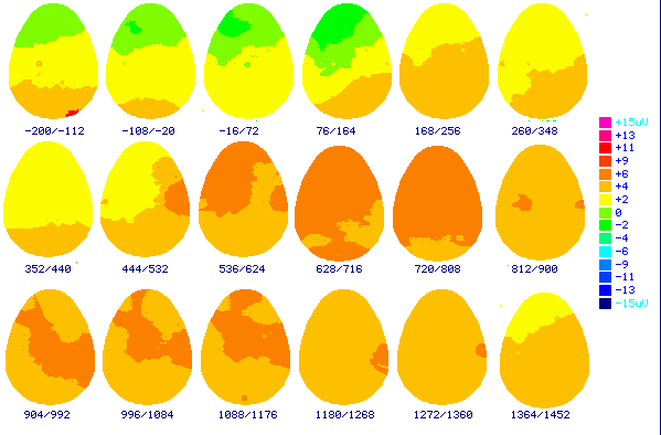
Figure (3.4.6a) shows the top view cartoon brainmaps made from the non-learners (nLFr) subtracted from the learner's (LFr) grand average ERP elicited with the first quartile trial answers. The numbers below each brainmap indicates the time in milliseconds when the map was computed. These results indicate 200msec before stimulus to 1500msec after stimulus. Color scale displays brain potentials from +15
m n in pink color, and –15 m n in dark blue. Frontal to the top, occipital to the bottom of the brain mapsThe third quartile trials (3rd fifty) figure 3.4.6c showed the same pattern as the first and the second quartile of learning trial with more positive activity over all brain areas. The positivity was more over the frontal area, temporal bilaterally and centrally. The activities over the brain areas became very low started to diminish gradually about 800msec post-stimulus, and there were some changes over the parietal, the central, and the temporal, but with no significant changes to the end of the task.
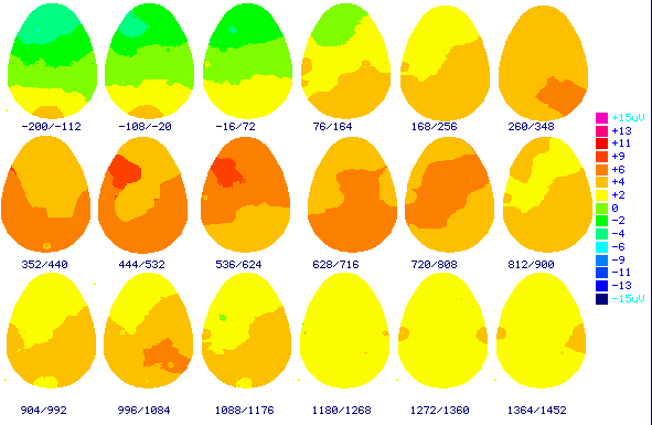
Figure (3.4.6b) shows the top view cartoon brainmaps made from the non-learners (nLFr)
subtracted from the learners (LFr) grand average ERP elicited with the second quartile trial answers. The numbers below each brainmap indicates the time in milliseconds when the map was computed. These results indicate 200msec before stimulus to 1500msec after stimulus. Color scale displays brain potentials from +15 m n in pink color, and –15 m n in dark blue. Frontal to the top, occipital to the bottom of the brainmaps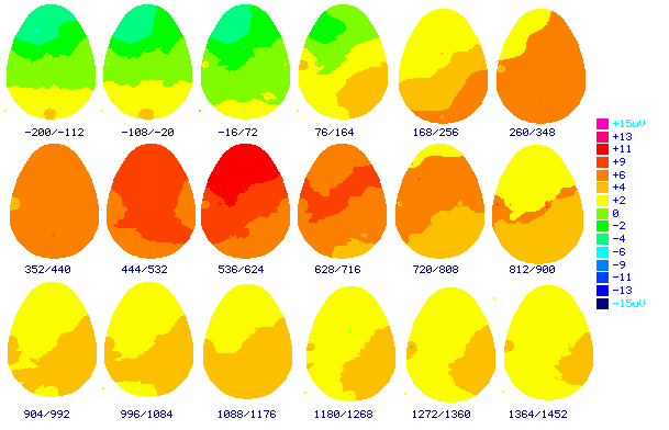
Figure (3.4.6c) shows the top view cartoon brainmaps made from the non-learners (nLFr)
subtracted from the learners (LFr) grand average ERP elicited with the third quartile trial answers. The numbers below each brainmap indicates the time in milliseconds when the map was computed. These results indicate 200msec before stimulus to 1500msec after stimulus. Color scale displays brain potentials from +15 m n in pink color, and –15 m n in dark blue. Frontal to the top, occipital to the bottom of the brain mapsThe fourth quartile trials (4th fifty) figure 3.4.6d showed the early started positive activities over the occipital area just post-stimulus and extended later to appear all over the brain areas. The parietal, central, occipital and posterior temporal areas showed bilateral positive activity from about 100msec post-stimulus to about 350msec and then the positive activity increased up to 900msec post-stimulus, but there were no too much differences between these areas. The frontal positive activity changes appeared over the right-hand side area from about 200msec and then distributed bilaterally up to about 900msec. The positive activity was localized over the frontal and temporal to the right-hand side from 250msec to 550msec post-stimulus. One second post-stimulus the activities over the brain areas did not show significant changes to the end of the task.
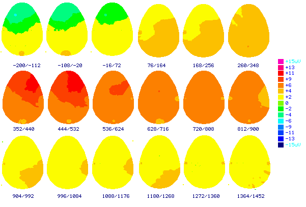
Figure (3.4.6d) shows the top view cartoon brainmaps made from the non-learners (nLFr)
subtracted from the learners (LFr) grand average ERP elicited with the fourth quartile trial answers. The numbers below each brainmap indicates the time in milliseconds when the map was computed. These results indicate 200msec before stimulus to 1500msec after stimulus. Color scale displays brain potentials from +15 m n in pink color, and –15 m n in dark blue. Frontal to the top, occipital to the bottom of the brain maps3.3.4.2. Group II learners (LFR n=15):
Figure (3.4.7 a, b, c, & d) show the cartoon brainmaps of the grand averaged event related potentials subtraction for the non-learners (nLFR) from the learners (LFR) in the second group during the four quartiles of the learning each quartile representing fifty trials.
The first quartile cartoon brainmaps (first fifty trials) in figure 3.4.7 a showed that there was no significant positive or negative pre-stimulus and then the positivity starts to appear post-stimulus over the occipital area followed by more positivity over the parietal area and distributed forward to be central then frontally where the positivity was stronger and stayed for longer time and bilaterally more to the right-hand side. After about 900msec and beyond the positive activity started to decrease gradually.
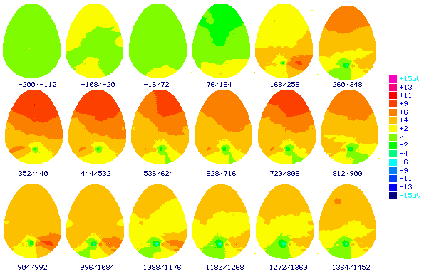
Figure (3.4.7 a) shows the top view cartoon brainmaps made from the group II learners (LFR) grand average ERP elicited with the first quartile trials answers. The numbers below each brainmap indicates the time in milliseconds when the map was computed. These results indicate 200msec before stimulus to 1500msec after stimulus. Color scale displays brain potentials from +15
m n in pink color, and –15 m n in dark blue. Frontal to the top, occipital to the bottom of the brain maps
The second quartile trials (2nd fifty) figure 3.4.7 b showed that there was positive activity appeared occipitally and negative activity frontally. The positive activity became general all over the brain areas about 250msec post-stimulus with more localized positive activity over the frontal area. There were positive activities over the posterior temporal area especially to the right-hand side. Less positive activity over the central area and it decreased as time progressed. It was bilateral with much deviation and extended more to the right-hand side. The positive activity diminished from about 1000msec to the end of the task.
The third quartile trials (3rd fifty) figure 3.4.7c showed the same pattern as the first and the second quartile of learning trial with more positive activity over all brain areas. The positivity was more over the frontal area and temporal bilaterally and centrally and started to diminish gradually but not as quickly as the first two quartiles.
The fourth quartile trials (4th fifty) figure 3.4.7d showed the early starting positive activities over the occipital area just post-stimulus which extended later to appear all over the brain areas. Generally there was not much change between the first quartile and the last quartile positive and negative activities, but there were little changes in these activities latencies
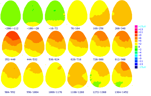
Figure (3.4.7 b) shows the top view cartoon brainmaps made from the learners (LFR) grand average ERP elicited with the second quartile trials answers. The numbers below each brainmap indicates the time in milliseconds when the map was computed. These results indicate 200msec before stimulus to 1500msec after stimulus. Color scale displays brain potentials from +15
m n in pink color, and –15 m n in dark blue. Frontal to the top, occipital to the bottom of the brain maps
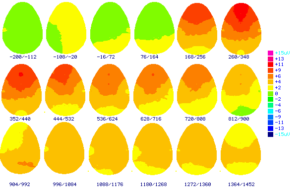
Figure (3.4.7c) shows the top view cartoon brainmaps made from the learners (LFR) grand average ERP elicited with the third quartile trials answers. The numbers below each brainmap indicates the time in milliseconds when the map was computed. These results indicate 200msec before stimulus to 1500msec after stimulus. Color scale displays brain potentials from +15
m n in pink color, and –15 m n in dark blue. Frontal to the top, occipital to the bottom of the brain maps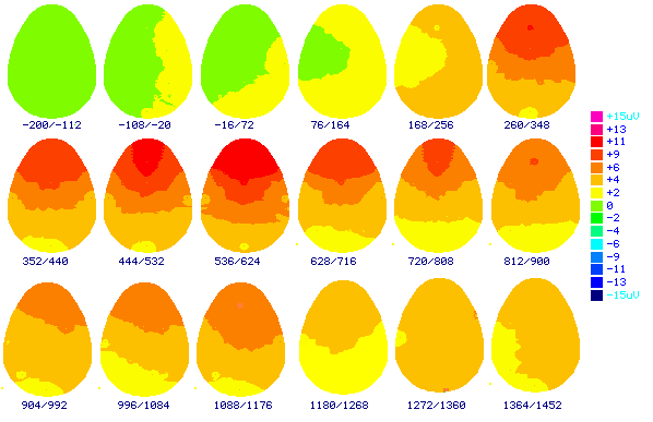
Figure (3.4.7d) shows the top view cartoon brainmaps made from the learners (LFR) grand
average ERP elicited with the fourth quartile trials answers. The numbers below each brainmap indicates the time in milliseconds when the map was computed. These results indicate 200msec before stimulus to 1500msec after stimulus. Color scale displays brain potentials from +15 m n in pink color, and –15 m n in dark blue. Frontal to the top, occipital to the bottom of the brain maps3.3.4.3. Group III learners (Lfr n=8):
Figure (3.4.8 a, b, c, & d) show the cartoon brainmaps of the grand averaged event related potentials subtraction for the non-learners (nLfr) from the learners (Lfr) during the four quartiles of the learning each quartile representing fifty trials.
The first quartile showed in figure 3.4.8a the generalized positive activities all over the occipital, parietal, central, anterior and posterior temporal areas and the maximum was over the frontal area especially to the right-hand side and started to diminish gradually from about 600msec post-stimulus to the end of the trials.
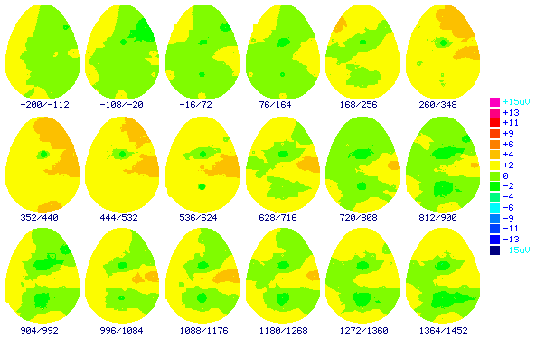
Figure (3.4.8a) shows the top view cartoon brainmaps made from the non-learners (nLfr)
subtracted from the learners (Lfr) grand average ERP elicited with the first quartile trial answers. The numbers below each brainmap indicates the time in milliseconds when the map was computed. These results indicate 200msec before stimulus to 1500msec after stimulus. Color scale displays brain potentials from +15 m n in pink color, and –15 m n in dark blue. Frontal to the top, occipital to the bottom of the brain mapsThe second quartile showed minimal changes, which means that there was no difference between the non-learners and the learner's brainmap. The positive activity became more from about 350msec to about 750msec and localized frontally to the right-hand side and bilaterally over the parietal, posterior temporal and occipital areas. From about 800msec latency and beyond the cartoon brainmaps showed that there were no significant positive or negative activity changes which indicate that there were no significant differences between the non-learners and the learners brain activities to the end of the task figure 3.4.8b.
The third quartile trials cartoon brainmaps showed in figure 3.4.8c that there were more differences between the learners and the non-learners brain activity during performing the task. There was a positive activity change starting early over the occipital area and then more positive changes appeared over the frontal area bilaterally from about 150msec and then more localized to the right-hand side. It decreased after about 1000msec. There were no significant differences between over the parietal, central, and temporal areas from the beginning to the end of the task.
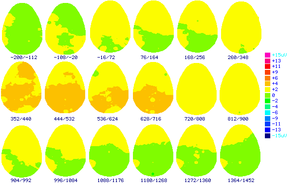
Figure (3.4.8b) shows the top view cartoon brainmaps made from the non-learners (nLfr)
subtracted from the learners (Lfr) grand average ERP elicited with the second quartile trial answers. The numbers below each brainmap indicates the time in milliseconds when the map was computed. These results indicate 200msec before stimulus to 1500msec after stimulus. Color scale displays brain potentials from +15 m n in pink color, and –15 m n in dark blue. Frontal to the top, occipital to the bottom of the brain mapsThe 4th quartile trials cartoon brainmaps shown in figure 3.4.8d showed more differences between the learners and the non-learners in brain activity. There were positive activity changes starting early over the occipital and the parietal area bilaterally from about 70msec post-stimulus to about 350msec. The frontal positive activity changes appeared over the right-hand side area from about 250msec and then distributed bilaterally to about 900msec. The positive activity became localized to the right hand side again from 900msec to 1200msec when started to decrease. There were no significant differences between the parietal, central, and temporal areas from about 350msec to the end of the task.
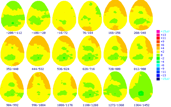
Figure (3.4.8c) shows the top view cartoon brainmaps made from the non-learners (nLfr)
subtracted from the learners (Lfr) grand average ERP elicited with the third quartile trial answers. The numbers below each brainmap indicates the time in milliseconds when the map was computed. These results indicate 200msec before stimulus to 1500msec after stimulus. Color scale displays brain potentials from +15 m n in pink color, and –15 m n in dark blue. Frontal to the top, occipital to the bottom of the brain maps
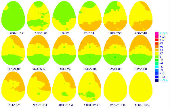
Figure (3.4.8d) shows the top view cartoon brainmaps made from the non-learners
(nLfr) subtracted from the learners (Lfr) grand average ERP elicited with the fourth quartile trial answers. The numbers below each brainmap indicates the time in milliseconds when the map was computed. These results indicate 200msec before stimulus to 1500msec after stimulus. Color scale displays brain potentials from +15 m n in pink color, and –15 m n in dark blue. Frontal to the top, occipital to the bottom of the brain maps3.3.4.4. Group IV learners (LfR n=6):
Figure (3.4.9 a, b, c, & d) show the cartoon brainmaps of the grand averaged event related potentials subtraction for the non-learners (nLfR) from the learners (LfR) during the four quartiles of the learning each quartile representing fifty trials.
The first quartile (1st fifty trials) figure 3.4.9a showed that there was a difference between the learners and the non-learners. The positive activity started early occipital and posterior temporal bilaterally from 100msec post-stimulus. Then extended over the parietal bilaterally and the anterior temporal to the right-hand side from 150msec to 450msec. The frontal area started very late from 550msec to 1200msec and then gradually decreased to the end of the task. Figure 3.4.9b showed the differences between the learners and non-learners. The positive activity over the frontal, central, anterior temporal and parietal areas bilaterally from 150msec to 1200msec and then decreased gradually to the end of the task.
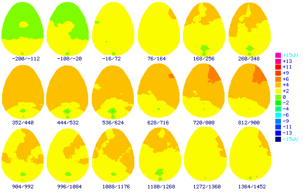
Figure (3.4.9a) shows the top view cartoon brainmaps made from the non-learners (nLfR) subtracted from the learners (LfR) grand average ERP elicited with the first quartile trial answers. The numbers below each brainmap indicates the time in milliseconds when the map was computed. These results indicate 200msec before stimulus to 1500msec after stimulus. Color scale displays brain potentials from +15
m n in pink color, and –15 m n in dark blue. Frontal to the top, occipital to the bottom of the brain maps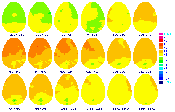
Figure (3.4.9b) shows the top view cartoon brainmaps made from the non-learners (nLfR) subtracted from the learners (LfR) grand average ERP elicited with the second quartile trial answers. The numbers below each brainmap indicates the time in milliseconds when the map was computed. These results indicate 200msec before stimulus to 1500msec after stimulus. Color scale displays brain potentials from +15
m n in pink color, and –15 m n in dark blue. Frontal to the top, occipital to the bottom of the brain mapsThe third quartile (3rd fifty trials) figure 3.4.9c showed frontal positive activity bilaterally and then showed more positivity from 350msec to 700msec and localized to the left-hand side. The positive activity over the parietal, posterior temporal started from 350msec to 1000msec. Decrease the positive activity from 1000msec to the end of the task.
The last fifty (4th quartile) showed that there were changes between the learners and the non-learners where the positive activity started at about 100msec over the occipital, parietal, posterior temporal areas bilaterally. The positive activities were over the central, anterior temporal bilaterally from 350msec. The positive activity over the frontal area was more than the other areas and it was bilateral at the beginning and more localized to the right-hand side to the end of the task figure 3.4.9d.
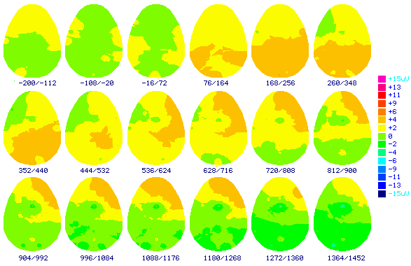
Figure (3.4.9c) shows the top view cartoon brainmaps made from the non-learners (nLfR)
subtracted from the learners (LfR) grand average ERP elicited with the third quartile trial answers. The numbers below each brainmap indicates the time in milliseconds when the map was computed. These results indicate 200msec before stimulus to 1500msec after stimulus. Color scale displays brain potentials from +15 m n in pink color, and –15 m n in dark blue. Frontal to the top, occipital to the bottom of the brain maps
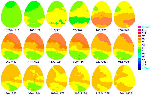
Figure (3.4.9d) shows the top view cartoon brainmaps made from the non-learners (nLfR) subtracted from the learners (LfR) grand average ERP elicited with the fourth quartile trial answers. The numbers below each brainmap indicates the time in milliseconds when the map was computed. These results indicate 200msec before stimulus to 1500msec after stimulus. Color scale displays brain potentials from +15
m n in pink color, and –15 m n in dark blue. Frontal to the top, occipital to the bottom of the brain maps3.3.4.5. Inter groups brainmaps comparison :
The above Figure (3.4.6d, 3.4.7d, 3.4.8d, 3.4.9d) show the cartoon brainmaps of the grand averaged event related potentials subtraction for the non-learners from the learners during the fourth quartiles of the learning each quartile representing last fifty trials in every group. The comparison between the learners of the all groups showed that the positive activity was localized in general to the frontal lobe and mainly to the right-hand side. The positive activity as well was well distributed over the parietal, central, anterior temporal, and occipital. All these positive activities were different from group to group in start point and their duration. Group II learners (LFR) showed the strongest positive activity in frontal area bilaterally, and especially to the right-hand side followed by the group I (LFr & nLFr) and group IV (LfR & nLfR) and on the least one is group III (Lfr & nLfr).
Figure 3.4.7a cartoon brainmaps showed the grand averaged event related potentials subtraction for the learners during the first quartiles of the learning (1st fifty trials). These subjects performed very well from the beginning of the task similar to their performance in last quartile of the task in the same group. When comparing figures (3.4.6d, 3.4.7d, 3.4.8d, and 3.4.9d), we found that there were no great differences between all these cartoon brainmaps.
We compared between the subjects effect for the brain activity elicited by the learners last quartile in every group and the learners first quartile in the second group (LFR) X all electrodes locations (F3, F4, F7, F8, ATL, ATR, C3, C4, T3, T4, T5, T6, TPL, TPR, P3, P4, O1, O2, FPZ, FZ, FCZ, CZ, PZ, POZ, OZ). The results revealed that there were no statistically significant differences for any of the groups (Table 3.4.7.)
|
Learning Group |
Amplitude |
df |
F |
|
LFr n=18 (4th quartile) LFR n=15 (1st quartile) |
6.12 ± 0.995.22 ± 1.01 |
(1,14) |
62.41 |
|
LFR n=15 (4th quartile) LFR n=15 (1st quartile) |
6.45 ± 1.095.22 ± 1.01 |
(1,14) |
53.37 |
|
Lfr n=8 (4th quartile) LFR n=15 (1st quartile) |
4.88 ± 1.125.22 ± 1.01 |
(1,7) |
33.17 |
|
LfR n=6 (4th quartile) LFR n=15 (1st quartile) |
4.99 ± 1.235.22 ± 1.01 |
(1,5) |
21.86 |
Table (3.4.7.) shows two ways repeated measures ANOVA test between subjects effect during the last quartile for the learners in each group and the learners first quartile in the second group (LFR) for all electrodes (F3, F4, F7, F8, ATL, ATR, C3, C4, T3, T4, T5, T6, TPL, TPR, P3, P4, O1, O2, FPZ, FZ, FCZ, CZ, PZ, POZ, OZ). *
£ 0.05, **£ 0.01, *** £ 0.001
3.4.5. Group V: Observers (Passive)
Grand average event related potentials were inspected visually for amplitude peaks and troughs. It can be seen that electrical activity was very similar in all parts of the brain pre-stimulus
All over the scalp the waveforms from all the electrodes superimposed for ERPs elicited by the all-trial stimuli show series of positive and negative peaks occurred with similar morphology and almost the same latency. The positive and negative waves beyond 200msec disappeared and the trace returned to the baseline and looks like the baseline (Figure 3.4.10.).
The top view cartoon brainmaps (Figure 3.4.11.) shows that there is no positive or negative activity before the stimulus. We could see the usual changes in the color with image perception. This activity was around the start point up to 200msec post-stimulus all over the brainmap especially frontal, parietal and occipital sites. Then the color changed again to the baseline level. From the color scale it can be seen that the amplitude was around zero m V ± 2 m V.
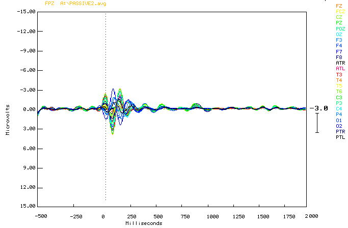
Figure (3.4.10.) shows the observers waveforms from all the electrodes superimposed for ERPs elicited by the all-trial stimuli. Y-axis shows amplitude in Microvolts (
m n ), and X-axis shows latency in milliseconds (ms). The black vertical dotted line marks the point of stimulus onset, and the horizontal black dotted line represents the baseline. Downward deflection represents the positivity. Upward deflection represents the negativity.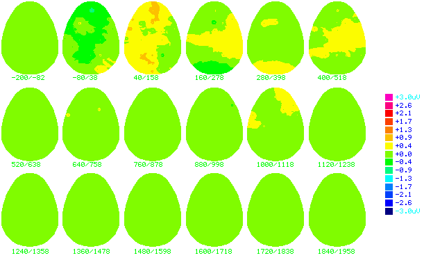
Figure (3.4.11.) shows the top view cartoon brainmaps of made from grand average ERP elicited with the all observers' trials. The numbers below each brainmap indicates the time in milliseconds when the map was computed. These results indicate 200msec before stimulus to 1500msec after stimulus. Color scale displays brain potentials from +15
m n in pink color, and –15 m n in dark blue. Frontal to the top, occipital to the bottom of the brain mapsStatistical analysis of the difference between subjects brain activity while performing the task for each quartile (50 trials). Between the subjects effect for the inter learner's group fourth quartile. The learner's groups by the electrodes locations during first versus last quartiles, and the correct answer trials versus the incorrect answers trials (See tables in appendices 5.5.2.)