Challenge
Start of topic | Skip to actions
Provenance Challenge: University of Southampton and ISI / USC
Participating Team
Team and Project Details
- Short team name: SOTON-ISI
- Participant names: Luc Moreau and Paul Groth
- Project URL: http://twiki.pasoa.ecs.soton.ac.uk/bin/view/PASOA/WebHome and http://www.isi.edu/ikcap/wings/
- Project Overview:
- Relevant Publications:
Workflow Representation
We represented the workflow as a Java application. We used a modified version of the Java code provided by Yogesh. The modifications we introduced consisted of transforming the code into POJOs (Plain Old Java Objects) so that we can use the IOC (Inversion of Control) pattern. This consisted of removing static methods and replacing those with method calls on objects. We introduced classes either for steps in the workflow or grouping of steps identified in the source code, for example, preload validation. We also introduced a main class that starts the workflow called Detector. In addition, an interface was introduced for each of the containers. The code can be run as POJOs, and for this, member variables are initialized with an explicit dependency injection. Alternatively, the code can be deployed in an EJB container, and for this, we annotation the code with the appropriate EJB annotations. We anticipate that there would be no problem running the code in Spring. Using an in-house tool, we captured process documentation (i.e. provenance information) according to the p-structure model. This tool deploys interceptors that produce process invocation when components are invoked. A brief description of the p-structure model can be found on the Southampton page from the first challenge. The process documentation generated for the PC3 Workflow according to the p-structure can be found here. The following is a depiction of the provenance of a database checked by the PC3 workflow generated from this process documentation. Click on the image above to see the larger pdf version. In this depiction, we see the provenance of a data item, i.e. the process that led to that data item. The data item itself is shown on the far right. The graph can be read as a timeline from left (earlier) to right (later). Each data item can be causally related to other data items, i.e. the outputs of a service are caused by the inputs of that service. The lines on the figure show relationships between data items. The provenance is represented as a tree, where as it is actually a directed acyclic graph. Where a data item occurs on multiple branches of the tree, it is marked with the same number, making it apparent that the same data item is referred to (from Southampton PC1 page).
Open Provenance Model Output
We output OPM following the OPM XML Schema found at http://openprovenance.org/model/v1.01.a. The XML can be found here. We also produced an RDF/XML serialization of the PC3 OPM (pc3opm.rdf) using the opmxml2rdf tool available in the OPM Toolbox at http://www.openprovenance.org. The RDF is produced according to the OWL Ontology underpinning Tupelo. Using the opm2dot tool also found in the OPM Toolbox, we generated the following graph. Click to see a high resolution pdf image.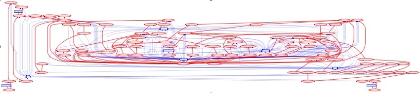 There are two accounts within the generated OPM to describe different levels of abstraction. In pc3opmcomm.xml, we also expose a third more detailed level of abstraction.
- The dependency_level (shown in red) account describes how artifacts were derived from other artifacts. Hence, in this account, we only find artifacts and WasDerivedFrom edges. There is no process or agent, and no other kind of edge. The dependency level tells us about the flow of data in the application.
- The process_level (shown in blue) adds information about how processes used and generated those artifacts. Hence, in this account, in addition to the artifacts of the dependency_level, we find, for each of them, the process that generated it (except for the very first artifact), and the processes that used it (except of the final artifacts in the computation).
- The communication_level (shown in black in pc3comm.pdf) adds information about how processes sent and received messages. Hence, in this account, in addition to the artifacts and processes of the previous two levels, we also find message send and message receive processes denoted by an appended "prod" and "recv" respectively and message artifacts denoted by "msg"
Query Results
Suggested Workflow Variants
Suggested Queries
Suggestions for Modification of the Open Provenance Model
Conclusions
-- LucMoreau - 19 Mar 2009 -- PaulGroth - 14 May 2009to top
| I | Attachment  | Action | Size | Date | Who | Comment |
|---|---|---|---|---|---|---|
| | pc3-all.jpg | manage | 319.2 K | 16 Apr 2009 - 05:09 | PaulGroth | |
| | pc3opm-small.jpg | manage | 58.4 K | 16 Apr 2009 - 05:29 | PaulGroth | |
| | pc3opm.pdf | manage | 43.4 K | 14 May 2009 - 22:06 | PaulGroth | |
| | pc3-all.pdf | manage | 37.3 K | 16 Apr 2009 - 05:34 | PaulGroth | |
| | pc3opm.xml | manage | 78.9 K | 14 May 2009 - 22:04 | PaulGroth | |
| | pc3.pstruct.xml | manage | 2342.8 K | 16 Apr 2009 - 17:14 | PaulGroth | |
| | pc3opm.rdf | manage | 114.2 K | 14 May 2009 - 22:21 | PaulGroth | |
| | pc3comm.pdf | manage | 118.4 K | 14 May 2009 - 22:09 | PaulGroth | |
| | pc3opmcomm.xml | manage | 265.3 K | 14 May 2009 - 22:09 | PaulGroth |
Edit | Attach image or document | Printable version | Raw text | More topic actions
Revisions: | r1.11 | > | r1.10 | > | r1.9 | Total page history | Backlinks
Revisions: | r1.11 | > | r1.10 | > | r1.9 | Total page history | Backlinks
Challenge.SotonUSCISIPc3 moved from Challenge.SotonPc3 on 04 Apr 2009 - 22:18 by PaulGroth - put it back